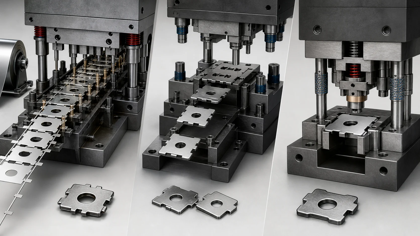
Progressive, transfer, and compound dies do not describe three quality levels. They describe different ways to move material and divide cutting and forming work across a press cycle.
TL;DR
A progressive die advances coil strip through multiple stations while the developing part remains connected to a carrier until cutoff. A transfer process separates a blank and moves it between stations, making it possible to reorient or support the part independently. A compound die performs multiple operations at one station in one press stroke and is often considered for comparatively flat parts where features such as a hole and outside profile benefit from being cut together.
Those definitions do not select the winning process. Geometry, form depth, strip layout, material behavior, annual volume, release size, press capacity, downstream operations, and tool ownership all matter. Ask stampers to quote a complete manufacturing route and expose the tooling and piece-price assumptions rather than specifying a die type from a product photo.
Start With Part Flow, Not a Die Label
Metal stamping is a family of cutting and forming operations performed with presses and dies. OSHA's mechanical-power-press definition covers machines that shear, punch, form, or assemble material by dies attached to slides [1]. That regulatory definition is useful for recognizing the equipment, but it does not turn every stamped part into the same production problem.
The practical distinction between die architectures is what happens to the material between operations:
- In a progressive die, stock commonly enters as coil-fed strip and advances by a controlled
pitch. Different stations pierce, form, coin, or cut while the part remains connected to the strip or carrier until separation.
- In a transfer process, the blank becomes an individual piece and a transfer mechanism moves
it through stations. The part can be lifted, indexed, rotated, or otherwise handled between operations when the transfer and tooling are designed to do so.
- In a compound die, two or more operations occur at one station during the same stroke. A
familiar example is piercing an internal feature while blanking the external profile.
PMA's training catalog explicitly treats single-station, progressive, and transfer dies as different die arrangements and treats cutting, forming, and drawing as operations that those arrangements may perform [2]. This distinction prevents a common sourcing mistake: deep draw is an operation, not automatically a fourth alternative to progressive or transfer tooling. A drawn part may use transfer tooling, progressive tooling, or a staged route depending on the part and production plan.
Quick Process-Selection Table
| Part and program signal | Architecture to investigate | Why it may fit | What can overturn the choice |
|---|---|---|---|
| Small or medium part, recurring high volume, several operations that can advance at a fixed pitch | Progressive die | Coil feed and simultaneous station work can support repeat production | Poor strip utilization, fragile carriers, deep forms, or difficult part exit |
| Deep or complex form that must be moved, rotated, or independently supported | Transfer die | Individual blanks can be manipulated between stations | Transfer access, press stroke, slower rate, blank preparation, or tool complexity |
| Flat part with internal and external cutting relationships important in one stroke | Compound die | Multiple cuts at one station can reduce station-to-station location effects | Forming sequence, tonnage concentration, part removal, or more complex geometry |
| Prototype or uncertain design with low initial demand | Stage tooling, laser and brake, soft tooling, or another low-commitment route | Avoids committing too early to a costly production die | Stable forecast or a geometry that needs production tooling to validate behavior |
| Large recurring program with complex forms and material-cost pressure | Transfer or optimized progressive route | Tooling and material utilization may dominate lifecycle cost | Available press line, automation, maintenance capacity, and launch timing |
AIDA's transfer-press guidance identifies part complexity and production volume as two basic selection criteria and notes that transfer systems can manipulate parts between operations [3]. That is useful OEM-scoped evidence, not a universal promise that transfer is always less wasteful or more flexible for every geometry.
Progressive Die: When the Strip Is Part of the Process
A progressive die performs different work at multiple stations during each stroke. While one station pierces the new strip, later stations may form or cut parts that entered several strokes earlier. Once the tool is running steadily, each stroke can produce a finished part or set of parts.
The strip layout is not leftover drafting work. It determines:
- feed direction and pitch;
- how the part remains attached and guided;
- where pilots can locate the strip;
- how forces are distributed across stations;
- the sequence of cuts and forms;
- scrap-web strength;
- material yield;
- burr direction and cutoff condition; and
- how the finished part exits without damage.
Longer, more complex progressive tools can impose off-center loads because the work is distributed across stations. AIDA's technical discussion of progressive and transfer dies highlights press connection spacing, frame characteristics, clearance, and load distribution as machine-selection concerns [4]. Buyers do not need to design the press, but they should verify that the supplier has matched the die to a suitable press rather than treating nominal tonnage as the only capacity number.
Progressive tooling is attractive when demand is real and stable enough to justify the tool, material can advance reliably, and the geometry can be created while attached to a carrier. It is not automatically economical simply because annual volume sounds high. A wide carrier, weak material utilization, high maintenance burden, or expensive tool change can dominate the result.
Transfer Die: When the Part Needs Independence
In transfer stamping, the process begins with an individual blank or separates the blank early, then moves the piece between stations. The transfer system may use fingers, rails, grippers, or other part-specific handling.
That independence matters when the part needs:
- substantial drawing or reshaping;
- access from different directions;
- rotation or inversion between operations;
- support that cannot come from a strip carrier;
- larger spacing between forming stations; or
- more freedom to optimize blank shape.
The transfer itself becomes part of the manufacturing process. Ask how the supplier detects a misfeed, double blank, dropped part, or incorrectly seated workpiece. Ask what surfaces the transfer contacts and whether cosmetic or functional faces can be marked. Ask how the process handles lubricant, scrap, and an interrupted cycle.
A transfer route can reduce material use in some applications because it is not forced to preserve the same carrier web as a progressive strip, but that outcome must be demonstrated with the actual blank and nesting plan. It is a cost model, not a slogan.
Compound Die: Several Operations at One Station
Compound dies combine operations at one station during one stroke. SME's stamping-die study guide includes compound dies in its formal training material, and PMA separates single-station die concepts from progressive and transfer arrangements [2][5].
Compound tooling is worth investigating when:
- the part is relatively flat;
- several cutting features can be created together;
- the relationship between an inside and outside profile matters;
- the part can be stripped and removed reliably; and
- concentrating operations in one station does not create an unacceptable force, tooling, or
maintenance problem.
Do not assume that “one stroke” means a simple or cheap tool. The die still has to guide, strip, clear scrap, manage cutting forces, protect critical edges, and eject the finished part. Parts requiring several forming stages may fit a progressive, transfer, combination, or hybrid route better.
The Economics: Tooling Is Only One Term
Compare alternatives using lifecycle cost:
program cost =
  tool design and build
  + validation and launch
  + quantity × piece price
  + expected maintenance and repair
  + material and scrap exposure
  + secondary operations
  + inspection and reporting
  + inventory and release-size cost
For two quoted routes, the simple crossover quantity is:
crossover quantity =
  (higher tooling cost - lower tooling cost)
  ÷ (higher piece price - lower piece price)
That arithmetic is only as good as the scope beneath it. Confirm whether the quoted tooling price includes design reviews, simulation, tryout material, samples, capability studies, spare details, shipping, installation, and customer approval. Confirm whether piece price assumes a minimum release, annual volume, material index, unattended rate, or customer-owned packaging.
Worked example
Suppose a staged route requires $18,000 in tooling at $1.42 per part, while a progressive route requires $92,000 in tooling at $0.68 per part.
($92,000 - $18,000) ÷ ($1.42 - $0.68) = 100,000 partsAt a clean 100,000-part comparison, the arithmetic reaches parity. The business decision still depends on design maturity, expected program life, cash timing, maintenance, material utilization, release sizes, and whether the forecast is credible.
What Belongs in a Stamping RFQ
Product definition
- Controlled drawing and 3D model
- Part number, revision, and units
- Datum structure and functional characteristics
- Burr direction, edge condition, flatness, and surface expectations
- Mating-part or assembly context where it affects forming
Material
- Alloy, grade, temper or condition, and governing specification
- Thickness and permitted variation
- Coil, sheet, or customer-supplied material constraints
- Grain-direction restrictions where function requires them
- Surface condition, prefinish, plating, or coating
- Substitution and approval rules
Program
- Prototype and production quantities
- Annual demand and expected program life
- Typical release size and forecast variability
- Launch date and sample milestones
- Spare-parts or service demand after production
Tooling and operations
- Tool ownership, payment milestones, and identification
- Storage, preventive maintenance, repair, and replacement responsibilities
- Required secondary work such as tapping, welding, cleaning, heat treatment, plating, or assembly
- Packaging, part orientation, and cosmetic protection
- End-of-program return, transfer, or disposition terms
Quality evidence
- First-article or production-approval requirements
- Characteristics to report
- Sampling, capability, or run-at-rate expectations
- Material and process certificates
- Lot traceability and record retention
- Change-notification and deviation process
Questions That Separate Real Capability From a Press List
- Which die architecture and press line are you proposing, and what part feature drives that
choice?
- What is the proposed material layout and estimated utilization?
- Which operations occur in the die and which occur afterward?
- What press characteristics matter beyond nominal tonnage?
- How are feed, part presence, transfer, and ejection faults detected?
- Which characteristics are most sensitive to tool wear, material variation, or setup?
- What preventive-maintenance interval and spare-detail strategy does the quote assume?
- Who owns the tool data, die, gauges, fixtures, and replacement components?
- What evidence is produced at launch and during recurring production?
- What happens to price and lead time if forecast or release quantity changes?
Safety Is a Qualification Question, Not an RFQ Shortcut
Buyers should not use an article to prescribe press-safeguarding methods. OSHA requires employers to use dies and operating methods designed to control or eliminate operator hazards, establish die-setting procedures, and record or mark die tonnage and stroke requirements [1]. OSHA also states that each press should be considered as a system including the press, controls, tooling, safeguarding, material handling, piecepart, and production requirements [6].
During supplier qualification, verify that the manufacturer has a real safety and maintenance system. Do not interpret a low quote as permission to ignore how the work is run.
A Restrained Next Move
Send the same controlled RFQ to a small set of stampers and ask each to show the proposed part flow, tooling scope, secondary operations, material utilization, and production assumptions. Use the U.S. Manufacturing Directory to research metal-stamping and tool-and-die capabilities, or use Intelligent Sourcing when the die route is still uncertain.
Related Articles
- Material Traceability: Heat Numbers, Lot Numbers, Batch Records, and Cut Pieces
- How to Source a Tool-and-Die Partner in the United States
- Supplier Quality Audit: What a Certificate Cannot Tell You
References
- Occupational Safety and Health Administration, 29 CFR 1910.217 — Mechanical power presses.
- Precision Metalforming Association, METALFORM EDU course catalog. Industry-association training source defining the learning scope for single-station, progressive, transfer, cutting, forming, and drawing operations.
- AIDA-America, Transfer Press Technology. Press-OEM guidance used only for transfer-system selection and part-manipulation concepts.
- AIDA-America, Off-Center Loading for Metal Stamping Presses. Press-OEM technical guidance used for press-loading considerations.
- SME, Sheet Metal Stamping Dies & Processes study guide. Industry training source.
- Occupational Safety and Health Administration, Mechanical Power Presses — Press Safety Considerations.