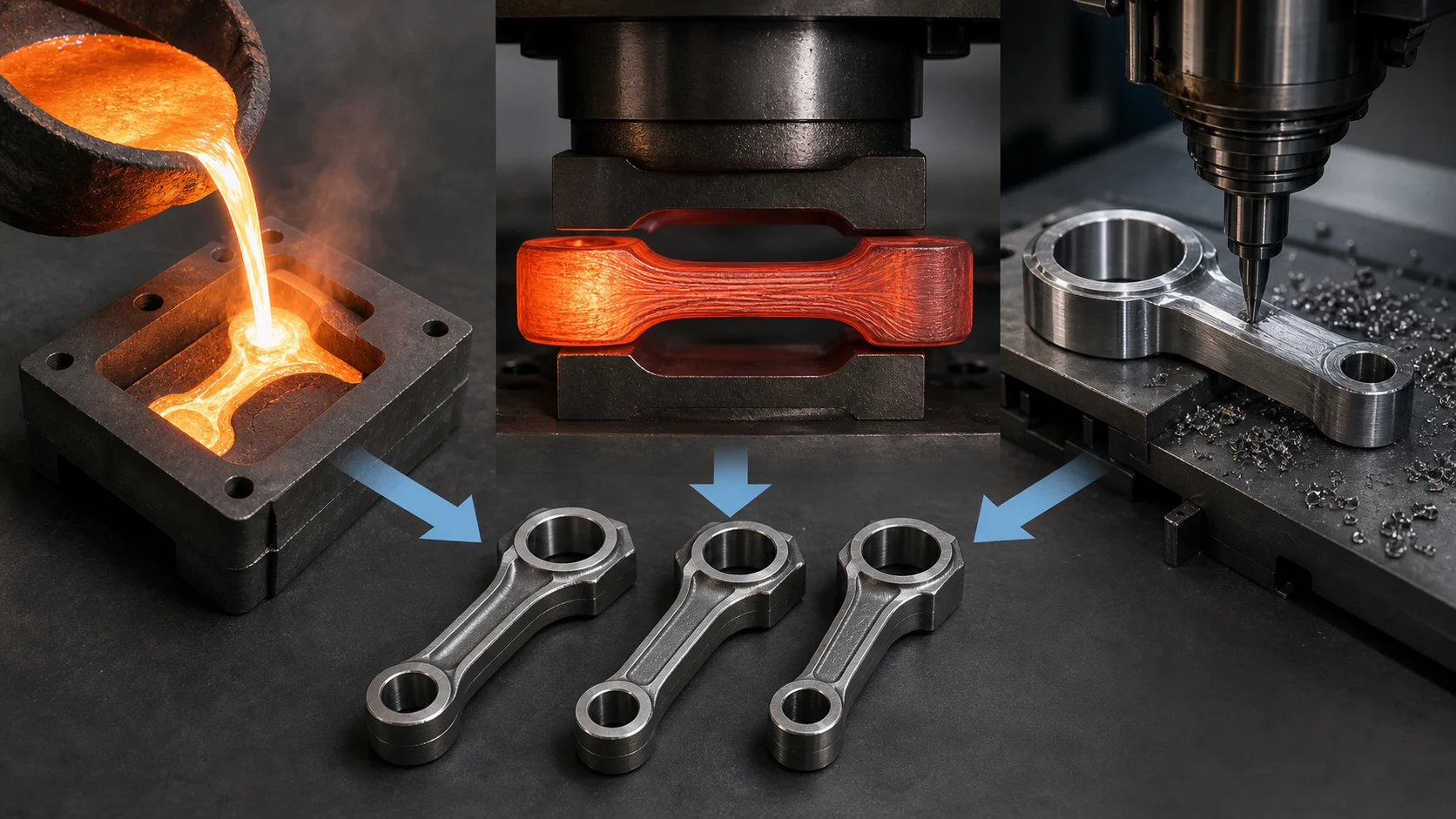
Select the starting process around the complete part route. Most production components are not cast, forged, or machined—they are cast or forged and then machined.
TL;DR
Machine from wrought stock when low tooling commitment, rapid revision, tight features, and low-to-moderate volume dominate. Consider casting when complex near-net geometry, internal passages, material distribution, and repeat volume justify pattern, mold, process development, and casting-quality controls. Consider forging when directional material flow, mechanical properties, fatigue or impact performance, and repeat production justify dies and forming development.
The actual route is often casting plus machining or forging plus heat treatment and machining. Compare complete delivered-part economics and qualification—not raw blank prices.
This Is a Starting-Stock Decision
The question is rarely whether a finished component should be “cast or machined.” Castings and forgings commonly need machining for interfaces, bores, sealing surfaces, threads, and precise datums. The real decision is which starting form creates the most capable and economical route.
NIST's conceptual process-planning framework treats process selection, manufacturing-resource selection, and cost estimation as connected decisions governed by product requirements and process knowledge [1]. That is the right mental model: the process cannot be selected from shape alone.
First-Pass Comparison
| Factor | Machine from wrought stock | Casting | Forging |
|---|---|---|---|
| Tooling commitment | Usually low to moderate | Moderate to high, process-dependent | Moderate to high |
| Design-change flexibility | High before material is cut | Lower after pattern/die commitment | Lower after die commitment |
| Complex internal geometry | Limited without assembly or specialized access | Strong with suitable cores/process | Limited |
| Material utilization | Can be poor for high buy-to-fly shapes | Often closer to net shape | Often closer to final envelope |
| Directional properties | Inherited from stock; cut orientation matters | Generally less directional than wrought flow | Can align grain flow with geometry |
| Surface and tolerance from primary process | Machining creates final features directly | Process-dependent; machining often required | Process-dependent; machining often required |
| Low volume | Often attractive | Process-dependent; tooling can dominate | Tooling often difficult to justify |
| High repeat volume | Cycle time and material removal can dominate | Tooling can amortize well | Tooling can amortize well |
| Internal discontinuity control | Wrought stock quality plus machining route | Porosity, shrinkage, inclusions, and process-specific conditions | Laps, folds, bursts, inclusions, and process-specific conditions |
These are tendencies. Investment casting, sand casting, permanent mold, die casting, open-die forging, closed-die forging, rolled rings, and machining processes occupy very different capability spaces.
Start With Functional Requirements
Define:
- loads and load directions;
- fatigue, impact, pressure, temperature, corrosion, and wear;
- alloy and allowed product forms;
- mass and material distribution;
- internal passages and inaccessible geometry;
- finished datum and tolerance requirements;
- surface condition;
- NDT and destructive-test expectations;
- annual volume and production life;
- launch timing and expected revisions;
- service and replacement demand; and
- qualification or customer-approval constraints.
Do not choose a process because the current CAD model resembles a familiar casting or billet. The model may not have been designed for either route.
When Machining From Wrought Stock Leads
Machining is often the strongest starting route when:
- volume is low or uncertain;
- geometry is still changing;
- delivery is urgent;
- approved plate, bar, tube, or billet is available;
- the part has accessible features;
- tooling investment cannot be justified;
- precise datums dominate the geometry;
- multiple variants share stock and setup; or
- the buyer needs a bridge route before production tooling.
Watch for:
- excessive material removal;
- long cycle time;
- deep pockets and poor tool access;
- distortion after roughing;
- stock-size or mill-minimum constraints;
- cut orientation relative to wrought grain;
- residual stress;
- chips and recycling economics; and
- a prototype route that cannot support production demand.
When Casting Leads
Casting can be attractive when the part needs:
- complex external shape;
- internal cavities or passages;
- variable wall and rib geometry suited to the selected process;
- consolidation of several components;
- near-net material placement;
- large or very small scale within a suitable casting process; and
- enough repeat demand to justify development.
DOE's metalcasting roadmap identifies tooling construction and process development as important contributors to casting lead time [2]. A casting quote should therefore distinguish pattern or die, core equipment, simulation, sampling, qualification, machining fixtures, and recurring production.
Key questions include:
- Which casting process and alloy?
- What draft, radii, parting, gates, risers, and machining stock are required?
- How are shrinkage and distortion managed?
- Which discontinuities are plausible, and where do they matter?
- What NDT, pressure test, sectioning, or mechanical tests apply?
- How is melt, heat, mold, cavity, and lot traceability preserved?
- Who owns and maintains tooling?
When Forging Leads
Forging can be attractive when the part benefits from:
- wrought material flow around the shape;
- high strength, toughness, fatigue, or impact demand;
- controlled reduction and working;
- pressure-containing or highly loaded geometry;
- near-net stock that reduces machining; and
- repeat demand that supports die and process development.
Evaluate:
- open-die, closed-die, rolled-ring, upset, or other route;
- billet specification and orientation;
- forging ratio or reduction requirements;
- grain-flow expectation;
- flash, draft, fillets, and parting line;
- heat-treatment sequence;
- scale removal and surface conditioning;
- machining envelope and datum transfer;
- macroetch, ultrasonic, mechanical, or other tests; and
- die ownership, life, repair, and replacement.
Forging does not make any geometry automatically superior. Grain flow, soundness, properties, and test evidence must be engineered and verified for the actual part.
Design Definition Changes by Starting Process
ASME Y14.8-2022 addresses drawing practices for castings, forgings, and molded parts [3]. Process-specific product definition may need:
- casting or forging datum targets;
- parting and mismatch limits;
- draft;
- stock and machining allowance;
- fillets and radii;
- flash or gate-removal areas;
- surface texture;
- permissible repair;
- discontinuity acceptance zones;
- test locations;
- tooling reference geometry; and
- final-machined requirements.
The raw-part drawing and finished-part drawing serve different decisions. Do not force a foundry or forge to manufacture only from a finished-machined model that omits primary-process controls.
Compare Complete Routes
| Route element | Machined stock | Cast route | Forged route |
|---|---|---|---|
| Raw material | Stock form, size, condition, and orientation | Charge/alloy and melt control | Billet/preform and orientation |
| One-time work | Programs, fixtures, gauges | Pattern/die, cores, process development | Dies, preforms, process development |
| Primary conversion | Saw and machine | Melt, mold, pour, shakeout, clean | Heat, form, trim, clean |
| Secondary | Stress relief, heat treat, finish | Heat treat, NDT, straighten, machine | Heat treat, NDT, straighten, machine |
| Qualification | First article and process evidence | Casting qualification and part evidence | Forging qualification and part evidence |
| Recurring risk | Cycle, tool wear, stock | Yield, tooling, melt/mold variation | Die life, material flow, forming variation |
Calculate break-even over realistic demand and revision scenarios. Include scrap, qualification, inventory, tooling replacement, and production recovery.
Selection Checklist
- Functional loads and property directions are defined.
- Alloy and approved product forms are known.
- Geometry has been reviewed for each candidate process.
- Primary-process and finish-machining tolerances are separated.
- Complete manufacturing routes and sub-tiers are quoted.
- Tooling ownership, life, storage, and transfer are explicit.
- Inspection and qualification address likely process conditions.
- Volume, program life, service demand, and revision risk are modeled.
- A bridge route and production route are distinguished where useful.
If more than one starting route remains plausible, use Intelligent Sourcing to find and compare facilities around the complete process chain rather than a single process label.
Related Articles
References
- National Institute of Standards and Technology, A Framework for Conceptual Process Planning Integrated With Conceptual Design.
- U.S. Department of Energy, Metalcasting Industry Technology Roadmap.
- American Society of Mechanical Engineers, ASME Y14.8-2022 — Castings, Forgings, and Molded Parts.