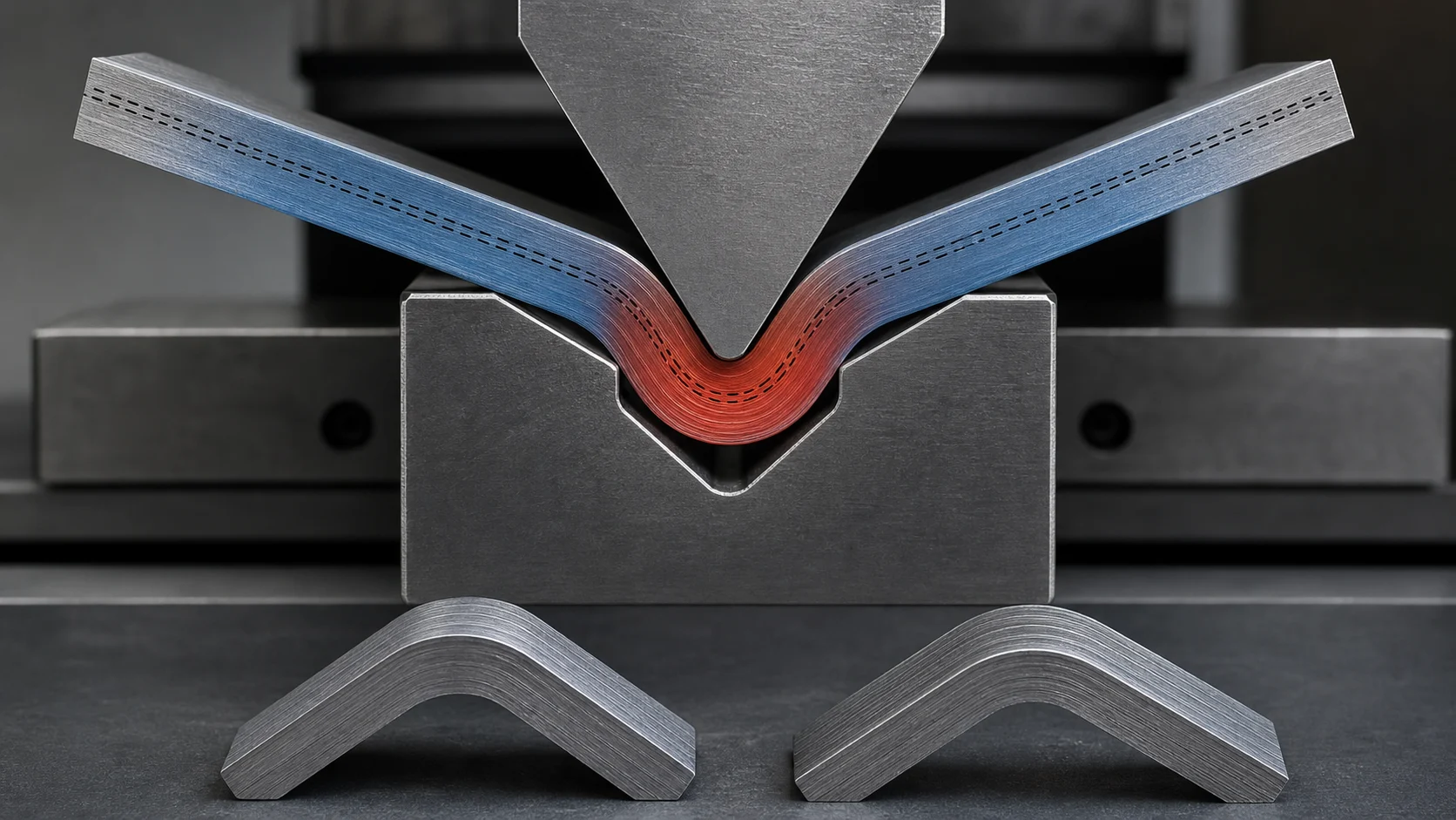
Bend radius, K-factor, and grain direction are linked to the actual material and tooling route. They should not be copied from a generic chart without shop validation.
TL;DR
Specify material grade, temper or condition, actual thickness range, inside bend radius, bend angle, critical flange dimensions, grain direction where it matters, and functional tolerances. Then let the fabricator validate tooling, bend sequence, K-factor or bend deduction, and springback compensation against the intended machine and stock.
The K-factor is a flat-pattern calculation input, not a universal material property. Air bending, bottoming, coining, roll forming, and dedicated tooling can produce different radii and elongation. A correct model requires the process that will actually make the part.
What Happens in a Bend
During bending, material toward the outside of the bend stretches while material toward the inside compresses. Between them is a neutral region whose location is commonly represented in flat-pattern calculations by a K-factor.
A common simplified bend-allowance relationship is:
Bend allowance = bend angle in radians × (inside radius + K × material thickness)
This is a useful geometric model. The correct K value must be established for the material, thickness, bend method, tooling, radius, and shop practice. It is not safely transferable from a random online table.
AMADA's press-brake technical publication describes the K-factor as representing the shifted neutral axis used to calculate bend allowance and notes that material type, strength, thickness, and grain direction affect bending behavior [1].
Define the Inputs That Actually Control the Part
| Input | Why it matters |
|---|---|
| Material specification | Different alloys behave differently |
| Temper or condition | Strength and ductility change forming limits and springback |
| Thickness and tolerance | Changes radius formation, tonnage, and flat length |
| Rolling direction | Affects bendability and fracture risk |
| Bend method | Air bend, bottom, coin, wipe, roll, or special forming behave differently |
| Punch and die | Establish contact, opening, nose, load, and formed radius |
| Angle and radius | Drive elongation, springback, and clearance |
| Flange and feature location | Can constrain tooling and cause distortion |
| Surface direction | Cosmetic grain or finish may constrain blank orientation |
Provide mill direction where it is known and important. Do not call a cosmetic brush direction “grain” without distinguishing it from metallurgical rolling direction.
Minimum Bend Radius Is Conditional
NIST-hosted metallurgy reference material explains that minimum safe bend radius depends on yield strength, design, dimensions, and tooling condition; it also notes that springback varies with strength, radius, and thickness [2]. Material handbooks can provide starting recommendations for specific alloy and condition, but test the actual stock when fracture consequence is high or the bend is near the published limit.
Risks of an overly tight radius include:
- exterior cracking;
- excessive thinning;
- coating damage;
- distortion around nearby holes;
- tooling overload;
- marking or galling;
- unpredictable angle; and
- reduced fatigue performance.
If the radius is not functionally critical, specify a practical minimum or range and let the fabricator use proven tooling.
Air Bending Does Not Simply Copy the Punch Radius
In air bending, the material contacts the punch and die shoulders without being fully pressed into the die. The formed inside radius is strongly influenced by the die opening and material response. Bystronic's vendor guidance notes this relationship and warns that tooling rules are approximate and process-specific [3].
Therefore:
- a modeled radius should reflect the intended V-die;
- different shops may need different flat patterns;
- changing the die opening can change radius and bend deduction;
- using several unnecessary radii increases tool changes and cost; and
- a supplier should confirm the radius it can repeat.
Bottoming and coining behave differently. Do not use an air-bend calculation without knowing the forming method.
Grain Direction Changes Bendability
Rolled sheet and plate can have direction-dependent properties. A bend line perpendicular to rolling direction bends the material across the rolling direction; a bend line parallel to rolling direction bends with it.
The NIST-hosted metallurgy reference states that the most severe bends can generally be made across the rolling direction and recommends angling multiple severe bends when they cannot all be oriented favorably [2]. Exact limits depend on material and condition.
Use grain direction deliberately when:
- the bend radius is near minimum;
- the alloy or temper has limited ductility;
- fatigue or fracture consequence is high;
- a long bend exposes anisotropy;
- several bends conflict;
- the sheet has directional surface finish; or
- nesting efficiency tempts rotation.
State whether rotating the blank is prohibited, allowed, or subject to approval.
Springback Is a Process Output
After load removal, elastic recovery changes angle and sometimes radius. Springback generally increases with stronger material and a larger radius-to-thickness relationship, but the actual response also depends on tooling, friction, method, batch variation, and prior processing.
Control it through:
- validated overbend;
- suitable bend method and tooling;
- material and thickness control;
- in-process angle measurement;
- crowning and machine compensation;
- consistent orientation;
- sample development; and
- recorded setup values.
Do not tighten angle tolerance without defining how it is measured and which flange or datum controls the decision.
Design Around Tool Access
Review:
- minimum flange length for the selected die;
- hole and slot distance from the bend;
- bend relief at intersecting edges;
- collision of formed flanges with punch, die, ram, or machine;
- back-gauge access;
- bend sequence;
- hems, offsets, joggles, and closed sections;
- large-sheet handling;
- tooling segmentation; and
- whether fasteners or hardware are installed before forming.
A part can be geometrically valid in CAD and impossible to remove from standard tooling after the last bend.
Flat Pattern Ownership
Choose one controlled arrangement:
- Buyer-controlled flat: the buyer supplies and approves the developed blank and bend model.
- Supplier-controlled flat: the buyer controls finished geometry; the supplier develops the
flat with its bend database.
- Joint qualification: the supplier develops the flat, samples are approved, and the
production flat becomes a controlled manufacturing artifact.
Do not send both a dimensioned flat and a conflicting formed drawing without an order of precedence.
Inspection Strategy
Inspect the formed part in its functional condition:
- define primary datums;
- establish restraint or free-state rules;
- identify which angle, radius, flange, and hole relationships are functional;
- distinguish reference flat dimensions;
- allow for flexible-part behavior;
- specify measurement location along long bends; and
- use boundary samples for cosmetic marking where appropriate.
For production control, record material lot, thickness, orientation, machine, tool set, program, bend sequence, and critical results.
Design-Release Checklist
- Material, temper, thickness, and finish are specified.
- Inside radius is manufacturable and only tight where functional.
- Grain/rolling and cosmetic directions are distinguished.
- Flat-pattern ownership and order of precedence are clear.
- Bend method and tooling assumptions have been reviewed.
- Short flanges, holes, reliefs, offsets, and collisions are resolved.
- Springback and angle tolerance have a realistic control plan.
- Formed-state datums and inspection condition are defined.
- Prototype approval preserves the production bend setup.
- Press-brake work is performed with appropriate safeguarding; OSHA identifies significant
point-of-operation hazards for these machines [4].
Use the U.S. Manufacturing Directory to identify sheet-metal fabricators, then review the actual material, tooling, machine envelope, and bend database.
Related Articles
- Laser, Waterjet, and Plasma Cutting
- Metal Stamping Process Selection
- Manufacturing Inspection Planning
References
- AMADA America, Excellence in Sheet Metal Starts at the Press Brake. OEM-scoped technical guidance.
- NIST Materials Data Repository, Elements of Metallurgy and Engineering Alloys — Deformation Processes.
- Bystronic, The Rules of Press Brake Tool Selection. OEM-scoped air-bending guidance.
- Occupational Safety and Health Administration, Powered Press Brakes.