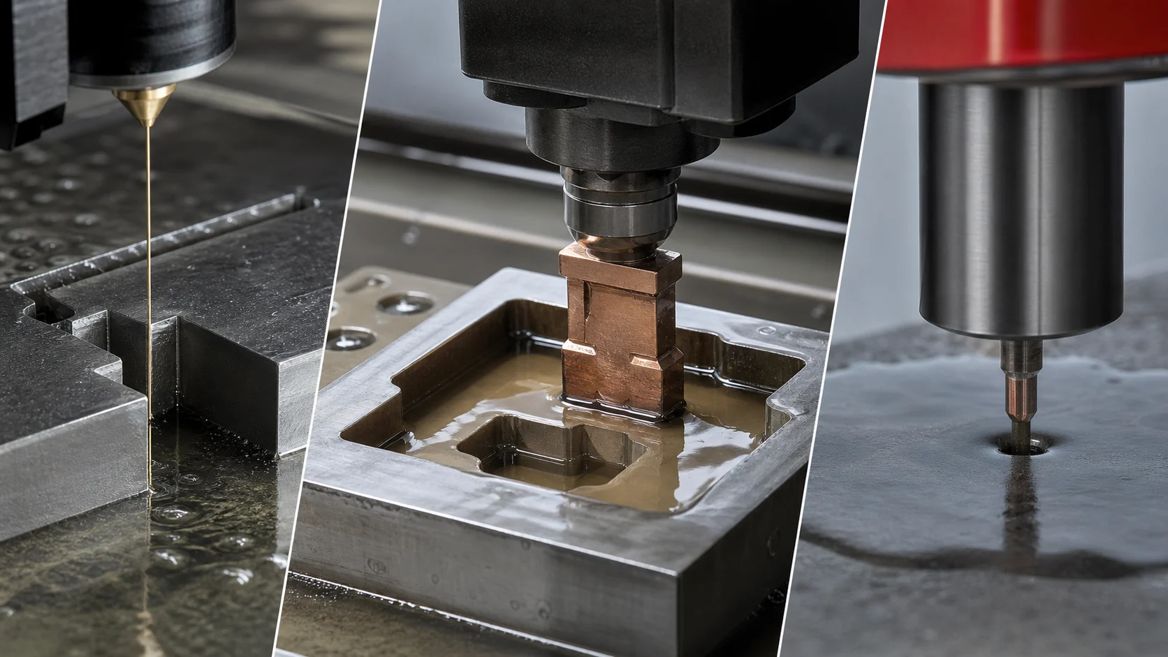
Wire, sinker, and hole-drilling EDM use controlled electrical discharges, but their electrodes and access paths make them useful for very different geometry.
TL;DR
EDM removes material through controlled electrical discharges between an electrode and a conductive workpiece separated by dielectric fluid. Wire EDM uses continuously fed wire to cut a path through the work. Sinker EDM uses a shaped electrode to generate a cavity or feature. EDM hole drilling uses a tubular or similarly configured electrode to create small or deep holes and is often used to make a wire-start hole.
Choose by geometry and access before discussing advertised accuracy. Wire needs a viable wire path and start strategy. Sinker needs an electrode and a way to flush the cavity. Hole drilling is optimized for holes, not arbitrary pockets. Every EDM route also needs an explicit surface-integrity and recast-layer requirement when the function makes it relevant.
One Removal Mechanism, Three Different Tools
Electrical discharge machining is a nontraditional removal process for electrically conductive materials. NIST describes EDM as obtaining shape through electrical discharges between an electrode and a workpiece separated by dielectric fluid [1]. There is no conventional cutting edge pushing a chip in the same way as milling or turning, but the process is not consequence-free: spark energy, flushing, electrode condition, workholding, thermal stability, and the remaining surface all matter.
The electrode determines the basic process:
- Wire EDM: a moving wire electrode traces a programmed cut.
- Sinker EDM: a shaped solid electrode is advanced into the workpiece.
- EDM hole drilling: a small tubular or specialized electrode creates a hole while dielectric
flow helps remove debris.
Makino's current EDM product family uses the same three categories—wire, sinker, and EDM drilling—which makes the terminology useful in supplier and machine-capability discussions [2]. An OEM product range demonstrates available machine architectures; it does not establish what every EDM supplier can hold on a specific part.
Fast Process-Selection Table
| Geometry or requirement | Process to investigate first | Why | Quote questions |
|---|---|---|---|
| Through profile in conductive plate, insert, or block | Wire EDM | Wire can trace an internal or external contour through the work | Start hole, wire diameter, cut height, taper, slug control, skim cuts |
| Blind cavity, sharp internal detail, rib, pocket, or mold feature | Sinker EDM | A shaped electrode can reproduce cavity geometry without a through path | Electrode material, number of electrodes, orbit, flushing, wear compensation |
| Small, deep, or difficult hole in conductive material | EDM hole drilling | Tubular-electrode systems are designed to penetrate with dielectric flow | Hole diameter, depth, breakthrough, straightness, electrode access |
| Internal profile with no edge entry | EDM hole drilling plus wire EDM | A start hole gives the wire access to the internal cut | Start-hole location, recast allowance, threading reliability |
| Hardened conductive feature after heat treatment | Wire or sinker EDM depending on geometry | EDM does not rely on conventional cutting hardness in the same way | Material conductivity, distortion before EDM, finish passes, surface integrity |
| Nonconductive ceramic, polymer, glass, or composite | Usually not conventional EDM | The discharge circuit needs a conductive workpiece path | Alternative process or validated specialty method |
The table is a routing aid. Material condition, size, machine travel, submerged-work limits, accuracy, finish, and supplier experience can change the answer.
Wire EDM: A Programmed Cut Through the Work
Wire EDM continuously advances electrode wire through guides while the machine moves the wire relative to the workpiece. Makino's technical tutorial describes modern wire machines as CNC systems with X, Y, U, V, and Z positioning that can offset upper and lower guides for tapered or three-dimensional cutting [3].
Wire EDM is a strong candidate for:
- punch and die sections;
- extrusion dies;
- gears, splines, keyways, and fine through profiles;
- hardened tool-steel components;
- narrow slots and internal contours;
- parting additive-manufactured components from build plates; and
- test-specimen or precision-section removal.
NIST's additive-manufacturing guidance explicitly discusses wire EDM as a method of separating parts from a build platform and notes that the work is commonly submerged or flooded with dielectric fluid [4]. That is one documented application, not a general accuracy guarantee.
What buyers miss about wire access
An external contour can often be entered from an edge. A closed internal contour needs a threading or start hole unless the feature already provides access. The shop must also manage the slug: when the inner piece breaks free, it cannot be allowed to tip, jam, damage the part, or interrupt an unattended cut.
The wire has physical diameter and operates across a spark gap. The programmed path compensates for that effective cutting width, but tiny internal radii are still constrained by wire size, machine settings, flushing, and cut strategy. Do not dimension a perfectly sharp internal corner and assume “EDM can do it” resolves the geometry.
Rough cuts and skim cuts
A first cut prioritizes material removal. One or more skim cuts can improve size, straightness, surface finish, and surface condition. Ask the supplier to state the quoted number of passes and the assumptions behind them. A one-pass quote and a multi-skim quote are not equivalent scopes.
Sinker EDM: The Electrode Creates the Cavity
Sinker EDM—also called ram, die-sinking, or cavity EDM—uses an electrode shaped to create the required feature. The electrode is commonly graphite or copper, although the choice depends on the application. The machine controls the spark gap as the electrode advances, often with orbital motion and programmed finishing conditions.
Sinker EDM becomes compelling when the geometry is blind or cannot be swept by a wire:
- mold cavities and ribs;
- blind keyways or pockets;
- sharp internal features;
- logos, textures, and shaped recesses;
- intricate die details; and
- features in hardened conductive materials.
The electrode is part of the job cost. It must be designed, manufactured, inspected, held, and located. Complex work may require separate roughing and finishing electrodes or several electrodes to control wear. A low sinker-EDM piece price that omits electrode cost is not a complete comparison.
Flushing is a geometry issue
Every discharge creates debris that must leave the spark gap. Deep narrow cavities, ribs, and poorly vented features can make flushing difficult. Ask how the proposed electrode, orbit, jump cycle, and dielectric delivery clear debris without creating unstable machining or uneven wear. “Can burn the shape” is not yet a production plan.
EDM Hole Drilling: Access and Small-Hole Work
EDM drilling uses a small electrode, commonly tubular, with dielectric flow through or around the tool. It is used for:
- wire-EDM start holes;
- cooling holes;
- vent holes;
- deep, small-diameter holes;
- holes in hard conductive alloys; and
- features where conventional drill access or tool life is problematic.
The relevant quote inputs are not only nominal diameter and depth. State:
- entry and exit surfaces;
- whether breakthrough is allowed to mark another feature;
- angle and access direction;
- positional and straightness requirements;
- acceptable taper;
- edge and recast requirements;
- whether the hole is functional or only a wire start; and
- how the result will be verified.
A supplier with wire and sinker machines does not automatically have a production hole-drilling machine, the required electrode range, or the metrology to validate a difficult aspect ratio.
Surface Integrity Is Part of the Requirement
EDM is a thermal process at the local discharge site. NIST reports that EDM can produce a recast or damage layer that differs from the base material and may be harder or more brittle depending on material and process [1]. In NIST's specific Charpy-specimen study, the observed layer and test result were evaluated for particular steels and machining combinations; those findings should not be generalized into “EDM damage never matters.”
The engineering question is functional:
- Is the EDMed surface highly stressed or fatigue critical?
- Is it a sealing, bearing, sliding, or cosmetic surface?
- Will a later grinding, polishing, lapping, or chemical process remove affected material?
- Does the controlling drawing or specification limit recast, microcracking, or heat-affected
material?
- Is metallographic verification required?
Makino's technical material likewise describes recast and heat-affected layers as process considerations and explains that discharge conditions and finishing strategy influence the result [5]. Treat that as OEM process guidance. Put the actual acceptance requirement in the contract rather than relying on the machine brand.
Accuracy Claims Need a Complete Context
“EDM holds tenths” is not a quote. Dimensional outcome depends on:
- machine and axis configuration;
- work envelope and workpiece mass;
- dielectric temperature and condition;
- workholding and datum transfer;
- wire or electrode choice;
- roughing and finishing passes;
- part height and taper;
- flushing and debris;
- electrode wear;
- thermal stabilization;
- measurement method and uncertainty; and
- whether the specified tolerance applies before or after later processing.
Ask for part-relevant capability and an inspection plan. A machine datasheet is evidence of potential, not evidence that your part will meet its requirements.
Worked Routing Example: A Hardened Die Insert
Consider a hardened tool-steel insert with:
- an outside rectangular profile;
- a closed internal opening with narrow corner radii;
- a blind relief pocket on one face;
- critical thickness and parallelism;
- a surface-integrity limit on working edges.
A plausible route might:
- grind reference faces and establish thickness;
- EDM-drill a start hole;
- wire-EDM the internal opening with specified skim cuts;
- wire-EDM the outside profile while controlling slug and part retention;
- sinker-EDM the blind relief;
- finish or condition designated working surfaces; and
- inspect profile, position, thickness, parallelism, finish, and any required recast evidence.
The lesson is not that this sequence is universally correct. It is that one part can require all three EDM modes plus grinding and inspection. The RFQ should describe the finished requirement and allow qualified suppliers to propose the controlled route.
EDM RFQ Checklist
- Controlled 2D drawing and 3D model
- Material grade, condition, and heat-treatment state
- Conductive coatings or material combinations identified
- Required through features and blind features distinguished
- Start-hole restrictions and permitted entry locations
- Minimum internal radius and slot-width requirements
- Taper, draft, and straightness requirements
- Critical surfaces and datum-transfer strategy
- Surface texture and surface-integrity requirements
- Recast, microcrack, or post-EDM finishing requirements where functional
- Quantity, repeat demand, and spare-tool expectations
- Electrode and fixture ownership
- Required inspection report and acceptance method
- Cleaning, corrosion prevention, packaging, and preservation
Questions for an EDM Supplier
- Which EDM mode or combined route are you proposing?
- What machine work envelope, axis configuration, and dielectric system apply?
- How will wire enter closed profiles and how will slugs be controlled?
- How many rough and finish passes are included?
- For sinker work, how many electrodes are included and who owns them?
- Which feature creates the flushing or electrode-wear risk?
- How will the part be referenced across grinding, wire, sinker, and inspection?
- What surface-integrity controls and post-EDM operations are included?
- How will small holes, tapers, and narrow radii be measured?
- Which assumptions would change price or lead time?
A Restrained Next Move
Separate through profiles, blind cavities, and holes in the product definition, then ask suppliers to propose the complete route and included finishing passes. Use the U.S. Manufacturing Directory to research EDM and tool-and-die capabilities, or use Intelligent Sourcing when access and process fit remain unclear.
Related Articles
- Surface Grinding: Reciprocating vs Rotary vs Double-Disc
- How to Source a Tool-and-Die Partner in the United States
- Surface Texture Beyond Ra: Lay, Cutoff, Location, and Function
References
- National Institute of Standards and Technology, Effect of Electrical Discharge Machining on Charpy Test Results from Miniaturized Steel Specimens. The material and result are study-specific; the source is used for the EDM mechanism and surface-layer boundary.
- Makino, EDM machine technology overview. OEM source used for the current wire, sinker, and hole-drilling process categories.
- Makino, Wire EDM Machine Centers Tutorial. OEM technical source used for wire-machine arrangement and axis concepts.
- National Institute of Standards and Technology, NIST Technical Note 1801: Measurement Science Roadmap for Metal-Based Additive Manufacturing. Used for the documented build-plate separation application and dielectric context.
- Makino, The Case for Additive Technology in EDM. OEM technical source used only for recast, heat-affected-layer, flushing, and finishing-process considerations.